Case Prep: Transforaminal Lumbar Interbody Fusion (TLIF)
Case / Approach Snapshot
- Anatomy at risk: level localization, cord/cauda equina, exiting and traversing roots, dura, vertebral artery or segmental vessels, esophagus/trachea/pleura/viscera by approach, and fusion/instrumentation landmarks.
- Operative steps: position and pad carefully, confirm level, expose the planned corridor, decompress neural elements, reconstruct or instrument when indicated, verify alignment/hardware, and close with attention to hematoma and wound risk; use the detailed operative sequence and approach notes below as the step-by-step source.
- Rescue plans: wrong level, durotomy, neurologic change, vertebral artery/visceral/pleural injury, graft or hardware problem, epidural hematoma, dysphagia/airway issue, and infection prevention/escalation.
- Figures: review Figures, Imaging & Video and the Curated Image Set; embedded local figures should remain open-access, public-domain, or otherwise reusable with attribution.
- Papers: review High-Yield Literature for seminal sources, modern reviews, and outcome data specific to this page.
One-Liner
[Age]yo [M/F] with [lumbar spondylolisthesis / recurrent disc herniation / degenerative disc disease / spinal stenosis] at [L_-S_] presenting with [back pain/radiculopathy/neurogenic claudication] planned for [minimally invasive / open] L_-S_ TLIF with pedicle screw fixation.
Figures, Imaging & Video
🎥 Operative video — search operative video on YouTube ▸ · The Neurosurgical Atlas ▸
🧭 Operative approach: Posterior thoracolumbar approach — detailed corridor setup, step-by-step technique & figures
Neurosurgical Atlas · AO Spine / Surgery Reference · Radiopaedia · PubMed Central — operative figures © linked; see media-sources.md
High-Yield Literature
- Lumbar interbody fusion: techniques, indications and comparison of interbody fusion options including PLIF, TLIF, MI-TLIF, OLIF/ATP, LLIF and ALIF — Mobbs RJ. Journal of spine surgery (Hong Kong) 2015. PubMed
- Endoscopic transforaminal lumbar interbody fusion: a comprehensive review — Ahn Y. Expert review of medical devices 2019. PubMed
- Minimally Invasive Transforaminal Lumbar Interbody Fusion (TLIF) — Badlani N. Clinical spine surgery 2020. PubMed
- Transforaminal lumbar interbody fusion using banana-shaped and straight cages: meta-analysis of clinical and radiological outcomes — Sebaaly A. European spine journal : official publication of the European Spine Society, the European Spinal Deformity Society, and the European Section of the Cervical Spine Research Society 2023. PubMed
- Transforaminal Lumbar Interbody Fusion For Lumbar Degenerative Disease: Patient Selection And Perspectives — Uçar BY. Orthopedic research and reviews 2019. PubMed
- Endoscopic transforaminal lumbar interbody fusion without general anesthesia: technical innovations and outcomes — Kolcun JPG. Annals of translational medicine 2019. PubMed
- Expandable Cage Technology-Transforaminal, Anterior, and Lateral Lumbar Interbody Fusion — Macki M. Operative neurosurgery (Hagerstown, Md.) 2021. PubMed
- Minimally Invasive Transforaminal Lumbar Interbody Fusion: Strategies for Creating Lordosis with a Posterior Approach — Tanasansomboon T. Neurosurgery clinics of North America 2023. PubMed
- Bibliometric analysis of transforaminal lumbar interbody fusion: research status, trends, and future directions — Wang X. EFORT open reviews 2023. PubMed
- Comparison of efficacy and safety between unilateral biportal endoscopic transforaminal lumbar interbody fusion versus uniportal endoscopic transforaminal lumbar interbody fusion for the treatment of lumbar degenerative diseases: a systematic review and meta-analysis — Ding Y. BMC musculoskeletal disorders 2024. PubMed
Curated Image Set
Open-access figures are embedded from PubMed Central articles and kept unique to this guide.
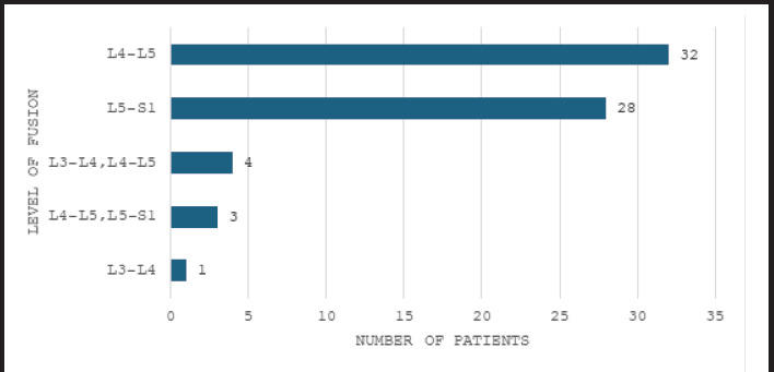 Figure 1. Levels of fusion in patients with spondylolisthesis following transforaminal lumbar interbody fusion surgery (n= 68). Source: Functional Outcome of Transforaminal Lumbar Interbody Fusion Surgery in Spondylolisthesis: An Observational Study — JNMA: Journal of the Nepal Medical Association 2025; CC BY.
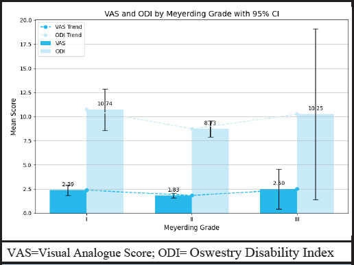 Figure 2. VAS and ODI by Meyerding grade with 95% CI in spondylolisthesis following transforaminal lumbar interbody fusion surgery (n= 68). Source: Functional Outcome of Transforaminal Lumbar Interbody Fusion Surgery in Spondylolisthesis: An Observational Study — JNMA: Journal of the Nepal Medical Association 2025; CC BY.
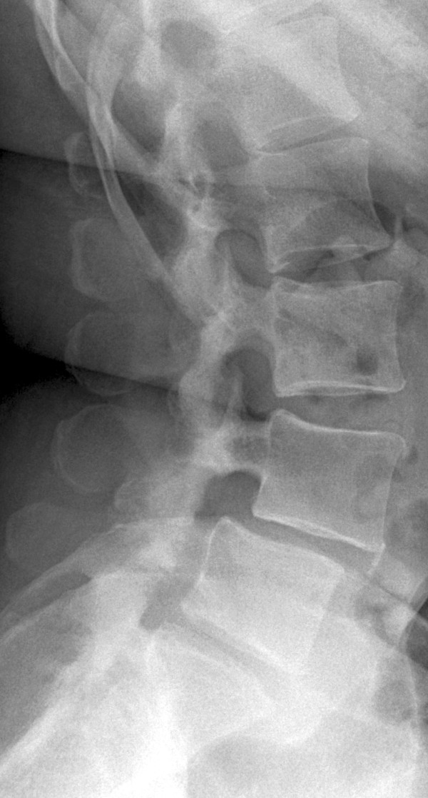 Figure 1. X-ray taken before the patient’s first surgery. Source: Set screw fracture with cage dislocation after two-level transforaminal lumbar interbody fusion (TLIF): a case report — Journal of Medical Case Reports 2015; CC BY.
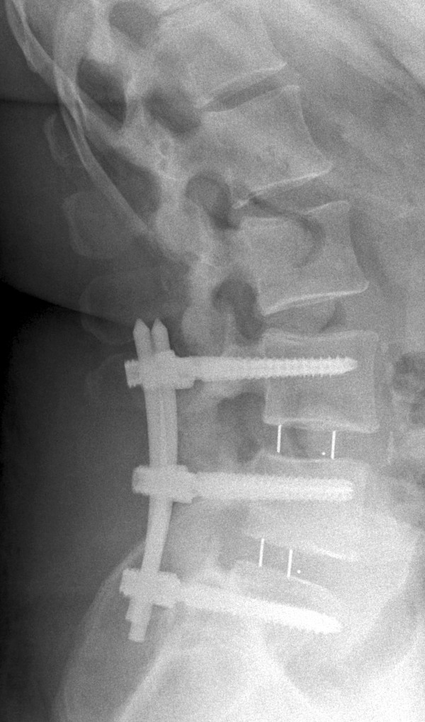 Figure 2. X-ray obtained after the patient’s first surgery. Source: Set screw fracture with cage dislocation after two-level transforaminal lumbar interbody fusion (TLIF): a case report — Journal of Medical Case Reports 2015; CC BY.
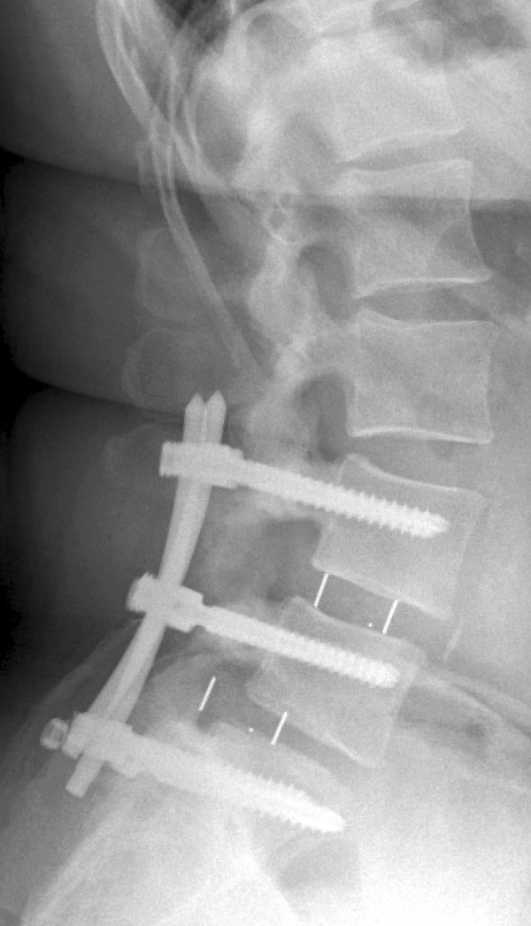 Figure 3. X-ray taken at first follow-up examination. Source: Set screw fracture with cage dislocation after two-level transforaminal lumbar interbody fusion (TLIF): a case report — Journal of Medical Case Reports 2015; CC BY.
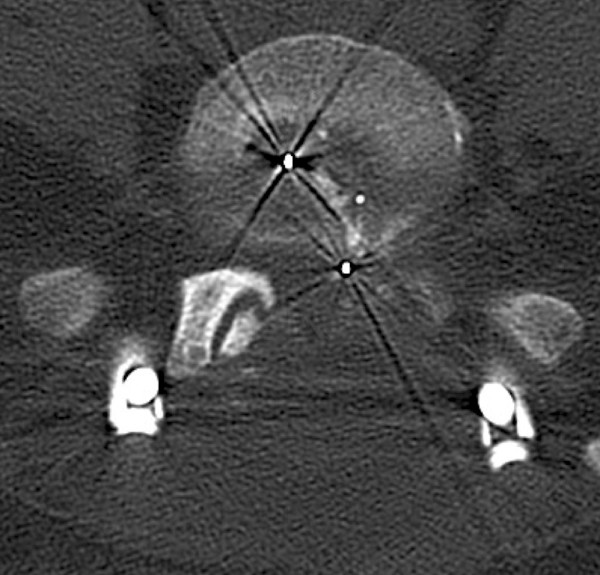 Figure 4. Computed tomographic scan taken at first follow-up examination. Source: Set screw fracture with cage dislocation after two-level transforaminal lumbar interbody fusion (TLIF): a case report — Journal of Medical Case Reports 2015; CC BY.
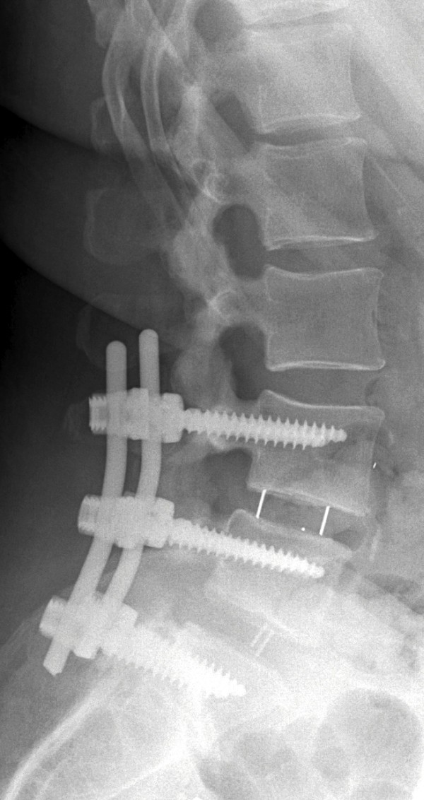 Figure 5. X-ray taken after the patient’s second surgery. Source: Set screw fracture with cage dislocation after two-level transforaminal lumbar interbody fusion (TLIF): a case report — Journal of Medical Case Reports 2015; CC BY.
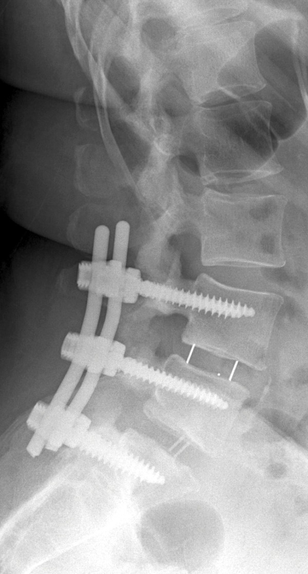 Figure 6. X-ray taken at the patient’s second follow-up examination. Source: Set screw fracture with cage dislocation after two-level transforaminal lumbar interbody fusion (TLIF): a case report — Journal of Medical Case Reports 2015; CC BY.
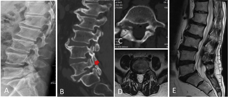 Figure 1. Lateral (A) radiograph of a 59-year-old male with L5 isthmic spondylolisthesis. The sagittal view (B) and transverse views(C) of preoperative CT and MRI (D, E) showed isthmic… Source: Comparison of O-arm navigation and microscope-assisted minimally invasive transforaminal lumbar interbody fusion and conventional transforaminal lumbar interbody fusion for the treatment of lumbar isthmic spondylolisthesis — Journal of Orthopaedic Translation 2020; CC BY-NC-ND.
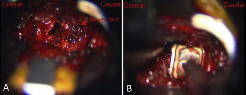 Figure 2. With the help of microscope, (A) the dural sac and nerve roots were exposed clearly; (B) the cage filled with bone fragments was inserted into the disc space. Source: Comparison of O-arm navigation and microscope-assisted minimally invasive transforaminal lumbar interbody fusion and conventional transforaminal lumbar interbody fusion for the treatment of lumbar isthmic spondylolisthesis — Journal of Orthopaedic Translation 2020; CC BY-NC-ND.
History of Present Illness
- Chief complaint: Low back pain / radicular leg pain / neurogenic claudication
- Duration:
- Failed conservative management: PT, medications, injections — duration ___
- Functional impact: Walking tolerance, work ability, ADLs
- Indications for fusion (vs decompression alone):
- Spondylolisthesis (Grade I-II) with instability or back pain
- Recurrent disc herniation (same level, prior discectomy)
- Degenerative disc disease with mechanical back pain (concordant on discography or isolated level)
- Stenosis with instability or deformity
- Revision surgery where facetectomy destabilizes the segment
Past Medical History
- Prior lumbar surgery (same level = revision; adjacent = ASD)
- Smoking (MUST quit — fusion rates significantly reduced)
- Diabetes (HbA1c — poor control impairs fusion and increases infection)
- Osteoporosis (DEXA T-score; affects screw purchase)
- Obesity (BMI — affects approach, healing, instrumentation)
- Depression/anxiety (predicts pain outcomes)
- Allergies:
- Medications:
Imaging Review
X-rays Lumbar (AP, Lateral, Flexion/Extension)
- Disc height loss
- Spondylolisthesis: Grade (Meyerding I-IV), degree of slip
- Dynamic instability on flexion/extension: > 4 mm translation or > 10 degrees angulation
- Lordosis: Segmental and overall lumbar lordosis
- Pelvic parameters: PI (pelvic incidence), PT (pelvic tilt), SS (sacral slope)
- PI = PT + SS
- Goal: LL (lumbar lordosis) ≈ PI ± 10
- Coronal alignment
MRI Lumbar Spine
- Disc degeneration at target level (Pfirrmann grade)
- Canal stenosis, foraminal stenosis
- Nerve root compression
- Adjacent level disease
- Paraspinal muscle quality (fatty infiltration)
- Modic changes (endplate inflammation)
CT Lumbar Spine
- Bony anatomy for screw planning
- Pedicle size and trajectory
- Facet arthropathy
- Existing fusion (if revision)
Labs
- CBC, BMP, Coags
- Type and screen
- HbA1c (< 8% preferred for elective fusion)
- Vitamin D, calcium
- Albumin/prealbumin (nutrition)
- DEXA scan results (if osteoporosis concern)
- Urinalysis (rule out UTI pre-op)
- Nicotine/cotinine level (smoking cessation documented)
Neurological Examination
- Complete lower extremity motor exam (myotomal)
- Sensory exam (dermatomal)
- Reflexes: Patellar, Achilles
- Straight leg raise
- Gait
- Bladder/bowel function
Surgical Planning
Case Logistics, OR Needs & Orders
- OR table/bed: Jackson/Allen/open-frame radiolucent table, or ProAxis/hinged table when sagittal alignment adjustment is useful; keep abdomen free for venous decompression.
- OR setup: radiolucent/Jackson table, fluoroscopy or O-arm/navigation, microscope/loupes for decompression, implant trays/graft ready for fusion, neuromonitoring for myelopathy/cord-risk cases, and postop brace plan confirmed.
- Special needs: arterial line/Foley/type-screen for long fusion/corpectomy, no long paralytic when MEPs are used, MAP/normotension for myelopathy or cord-risk cases, antibiotic redosing, and anticoagulation/DVT plan.
- Immediate postop orders: neuro checks by myotome/sensory level, airway/dysphagia watch for anterior cervical cases, CT/X-rays per construct, drain care, brace/activity orders, DVT prophylaxis timing, bowel regimen, and PT/OT mobilization.
Position
- OR table/bed: Jackson/Allen/open-frame radiolucent table, or ProAxis/hinged table when sagittal alignment adjustment is useful; keep abdomen free for venous decompression.
- Prone on Jackson table (or Wilson frame)
- Abdomen free — reduces epidural bleeding
- Arms: On armboards, < 90 degrees abduction
- Hips slightly flexed — reduces lumbar lordosis (easier to access disc space)
- Padding: All pressure points, eyes free
Approach: Posterior (Open or MIS)
Key Surgical Steps
Exposure and Pedicle Screws:
- Fluoroscopic level confirmation — count from sacrum
- Midline incision centered over target level (open) OR bilateral paramedian stab incisions (MIS)
- Subperiosteal dissection to expose spinous processes, laminae, facet joints bilaterally
- Pedicle screw placement:
- Identify entry point: Junction of transverse process, pars, and superior articular process
- L1-L4: Entry at junction of transverse process and SAP
- L5: Typically just lateral and caudal to the SAP
- S1: At junction of SAP and lateral sacral crest
- Use AP and lateral fluoroscopy (or navigation) to confirm trajectory
- Tap and feel for breach (anterior, medial, lateral, inferior)
- Place pedicle screws bilaterally at levels to be fused
- Confirm position with AP and lateral fluoroscopy
- Laminectomy/decompression:
- Remove lamina and ligamentum flavum at the target level
- Bilateral or unilateral decompression as needed
- Decompress the central canal and bilateral foramina
TLIF Interbody:
- Facetectomy: Complete unilateral facetectomy on the APPROACH SIDE (typically the more symptomatic side)
- This creates the transforaminal corridor to the disc space
- Preserve the contralateral facet to maintain some stability
- Identify the exiting and traversing nerve roots:
- Exiting root: Exits under the pedicle ABOVE (protect superiorly)
- Traversing root: Crosses the disc space medially (retract medially)
- Annulotomy: Incise the annulus at the posterior-lateral disc space
- Discectomy: Remove disc material with pituitary rongeurs, curettes, shavers
- Complete disc removal from one side across to the contralateral side
- Remove cartilaginous endplates (preserve bony endplates)
- Create flat, parallel surfaces
- Size the interbody cage:
- Trial cages for appropriate height and lordosis
- Assess distraction and restoration of disc height/foraminal height
- Graft the cage:
- Pack cage with local bone (from laminectomy/facetectomy) + allograft + bone substitute
- Pack additional graft anteriorly in the disc space before cage insertion
- Insert cage:
- Insert obliquely through the transforaminal corridor
- Impact into position — aim for ANTERIOR placement in the disc space (best load-bearing)
- Confirm position with fluoroscopy (lateral and AP)
- Cage should be within the anterior 2/3 of the disc space
- Rod placement and compression:
- Place rods bilaterally into pedicle screw tulips
- Compress across the construct to lock the cage and restore lordosis
- Final tighten all set screws
- Decorticate transverse processes and lay posterolateral bone graft (belt-and-suspenders fusion)
- Final fluoroscopy: AP and lateral — confirm screw position, rod alignment, cage position
- Closure:
- Irrigate copiously
- Hemostasis
- Drain (Hemovac/JP — optional)
- Fascial closure: 0 Vicryl interrupted
- Subcutaneous: 2-0 Vicryl
- Skin: Staples or subcuticular
Critical Anatomy
- Exiting nerve root — under the superior pedicle; at risk during facetectomy and disc space access
- Traversing nerve root — crosses the disc space medially; retract gently during discectomy
- Thecal sac / cauda equina — medially
- Great vessels — anterior to disc space (aorta, IVC, iliacs); do NOT plunge instruments anteriorly
- Pedicle medial wall — breached screw can enter canal and compress neural elements
- Segmental vessels — at each level on the vertebral body
Equipment
- C-arm fluoroscopy (or O-arm/navigation)
- Pedicle screw system (screws, rods, set screws, connectors)
- Interbody cage(s) and trials (TLIF cage — banana-shaped or bullet-shaped)
- Kerrison rongeurs, pituitary rongeurs, curettes
- High-speed drill
- Pedicle probe, tap, ball-tip probe (for checking screw trajectory)
- Bone graft: Local bone, allograft, bone substitute (DBM)
- Hemostatic agents
- Drain (optional)
- [BMP: controversial — typically NOT used in TLIF due to cage proximity to neural elements]
Monitoring
- SSEPs
- MEPs
- Triggered EMG (pedicle screw stimulation — threshold > 10-12 mA suggests intact medial wall)
Anesthesia
- General endotracheal anesthesia
- Arterial line (multi-level or complex revision)
- Foley
- Cefazolin 2g IV (redose every 4 hours)
- Tranexamic acid 1g IV (reduces blood loss)
- No paralytic (IONM)
- Keep MAP > 80
- Cell saver (revision cases)
- Keep well-hydrated (spine surgery bleeding)
Potential Complications
- Nerve root injury — radiculopathy from retraction, screw, or cage malposition; check monitoring
- Pedicle screw misplacement — medial breach (neural), lateral breach (usually well-tolerated), anterior breach (vascular at L5-S1)
- Cage malposition / migration — confirm with fluoroscopy; if retropulsed → emergent revision
- Dural tear / CSF leak — primary repair if possible; muscle patch + sealant; drain
- Pseudarthrosis (non-union) — 5-15%; smoking and diabetes are major risk factors
- Adjacent segment disease — long-term; instrumented fusion increases stress on adjacent levels
- Surgical site infection — 2-5%; risk increased with diabetes, obesity, smoking
- Epidural hematoma — if post-op neurological decline → emergent MRI → return to OR
Postoperative Plan
- Floor admission
- Neuro checks on arrival (compare to baseline)
- Ambulate POD0 or POD1 with PT
- Lumbar X-rays POD1 (AP and lateral — hardware position, alignment)
- CT scan for screw assessment (per surgeon preference — some do intraoperative)
- DVT prophylaxis: SCDs immediately; heparin SQ when hemostasis confirmed
- Pain management: Multimodal (acetaminophen, gabapentin/pregabalin, NSAIDs [some avoid for fusion concern], limited opioids, ice)
- Drain removal: When output < 50-100 mL/24h
- Diet: Regular
- Activity: Walk 4x daily; no BLT (bending, lifting, twisting) > 10 lbs x 6 weeks
- Lumbar brace: Per surgeon preference (evidence mixed; typically 6-12 weeks)
- Smoking cessation: CRITICAL for fusion
- Bone health: If osteoporotic — calcium, vitamin D, consider anabolic agent
- Follow-up: 2 weeks (wound); 6 weeks (X-ray); 3-6 months (CT for fusion); 1 year
- Fusion assessment: CT at 6-12 months showing bridging bone through cage and posterolateral
- Discharge: POD 1-3 typically
Chief-Level Case Review
Use these as the senior-level mental model for Transforaminal Lumbar Interbody Fusion (TLIF):
- Decision point: Localize twice and instrument once: numbering, transitional anatomy, prior hardware, rib count, navigation dataset, and fluoroscopic level confirmation are mandatory.
- Technical lever: Positioning is treatment: table choice, abdomen-free prone setup, alignment goals, shoulders/hips, eyes/plexus pressure, neuromonitoring baselines, and fluoroscopic access all change the case.
- Bailout: Protect neural elements by sequence: decompression before correction when needed, MAP support for cord risk, no long paralytic with MEPs, and immediate response to signal change.
- Postop watch: Finish with construct logic: decompression adequacy, screw purchase, alignment, fusion bed/graft, drain plan, brace/activity orders, postop CT/X-rays, and DVT timing.
Common Pimp Questions
Use these to pressure-test preparation for Transforaminal Lumbar Interbody Fusion (TLIF):
- What neurologic level and root are responsible for the presenting deficit?
- What is the decompression target and how will you know it is adequately decompressed?
- What instability, deformity, bone-quality, or fusion variable changes the construct?
- What vascular, visceral, dural, or neural structure is the main structure at risk?
- What postop brace, drain, mobilization, MAP, antibiotic, and DVT plan should be ordered?
Attending Preference Variables
Items that commonly vary by surgeon or institution:
- Positioning frame, arms, traction, and localization workflow: [attending-specific]
- Navigation/robot/fluoro use, screw system, graft/biologic choice, and drain threshold: [attending-specific]
- Neuromonitoring modality and MAP goal for myelopathy, deformity, or cord-risk cases: [attending-specific]
- Brace, Foley, antibiotics, mobilization, and DVT prophylaxis timing: [attending-specific]