
Case Prep: Vertebral Augmentation (Kyphoplasty / Vertebroplasty)
Case / Approach Snapshot
- Anatomy at risk: cord/roots, pedicles, pelvic fixation corridors, osteotomy levels, segmental vessels, thoracic/abdominal structures, and sagittal/coronal balance landmarks.
- Operative steps: confirm alignment goals, position and monitor, expose planned levels, place fixation, perform releases/osteotomies/decompression as needed, correct deformity gradually, verify hardware/alignment, and close dead space; use the detailed operative sequence and approach notes below as the step-by-step source.
- Rescue plans: neuromonitoring change, excessive correction or imbalance, blood loss/coagulopathy, durotomy, screw breach, junctional/fixation failure, and staged correction or hardware revision.
- Figures: review Figures, Imaging & Video and the Curated Image Set; embedded local figures should remain open-access, public-domain, or otherwise reusable with attribution.
- Papers: review High-Yield Literature for seminal sources, modern reviews, and outcome data specific to this page.
One-Liner
[Age]yo [M/F] with a painful [osteoporotic / pathologic] [T_/L_] vertebral compression fracture refractory to conservative care planned for [balloon kyphoplasty / vertebroplasty].
Figures, Imaging & Video
🎥 Operative video — search operative video on YouTube ▸ · The Neurosurgical Atlas ▸
Neurosurgical Atlas · AO Spine / Surgery Reference · Radiopaedia · PubMed Central — operative figures © linked; see media-sources.md
High-Yield Literature
- Vertebral augmentation — Amans MR. Handbook of clinical neurology 2021. PubMed
- Vertebral augmentation: an overview — Beall DP. Skeletal radiology 2023. PubMed
- Vertebral augmentation: How we do it — Raja J. Techniques in vascular and interventional radiology 2024. PubMed
- Vertebral Augmentation in Spine Surgery — Hoffmann J. The Journal of the American Academy of Orthopaedic Surgeons 2023. PubMed
- Vertebral augmentation for cancer patients — Marcia S. The British journal of radiology 2025. PubMed
- Vertebral augmentation with spinal implants: third-generation vertebroplasty — Manz D. Neuroradiology 2020. PubMed
- Percutaneous vertebral augmentation-pearls and pitfalls — Espahbodinea S. Journal of spine surgery (Hong Kong) 2023. PubMed
- Vertebral Augmentation — Munakomi S. 2026. PubMed
- Vertebral Augmentation of Cancer-Related Spinal Compression Fractures: A Systematic Review and Meta-Analysis — Mattie R. Spine 2021. PubMed
- Percutaneous Vertebral Augmentation and Thermal Ablation in Patients with Spinal Metastases — Tomasian A. Seminars in interventional radiology 2024. PubMed
Curated Image Set
Open-access figures are embedded from PubMed Central articles and kept unique to this guide.
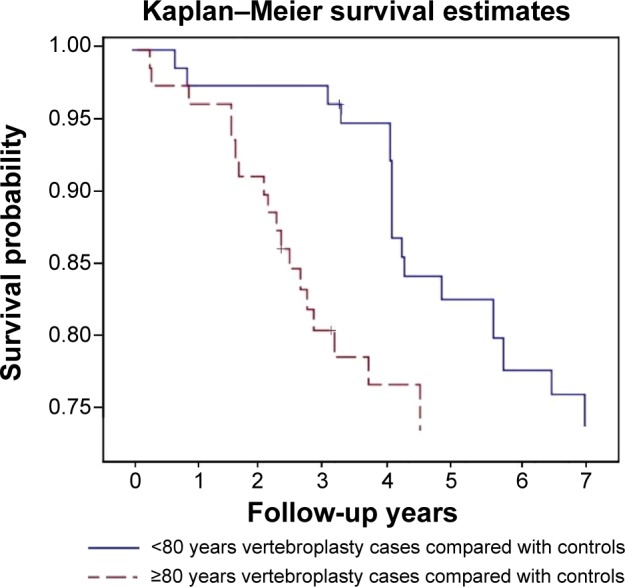 Figure 2. The frequency with which patients underwent a second procedure was particularly high in patients ≥80 years of age. Source: Repeated vertebral augmentation for new vertebral compression fractures of postvertebral augmentation patients: a nationwide cohort study — Clinical Interventions in Aging 2015; CC BY-NC.
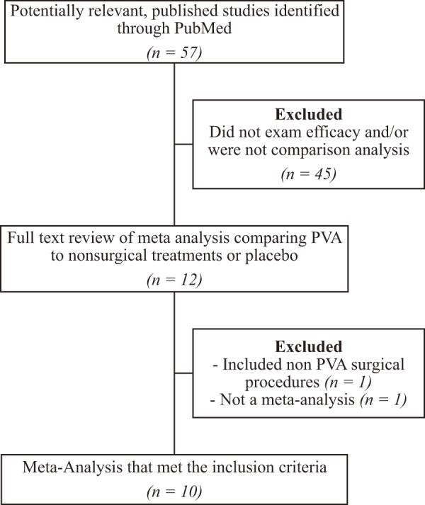 Figure 1.. This figure displays the methodology used in the literature search conducted for this review. Source: Efficacy of Vertebral Augmentation for Vertebral Compression Fractures: A Review of Meta-Analyses — Spine Surgery and Related Research 2018; CC BY-NC-ND.
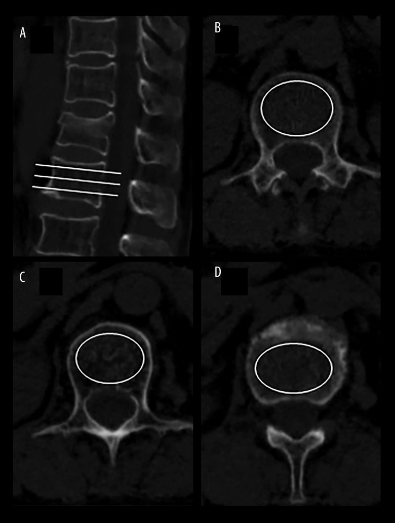 Figure 1. HU value was measured on CT scans by the largest elliptical region of interest. (A) CT sagittal image shown the positions of the 3 slices. (B) Inferior to the upper endplate. (C) Middle… Source: Risk Factors for New Vertebral Compression Fracture After Percutaneous Vertebral Augmentation: A Retrospective Study — Medical Science Monitor : International Medical Journal of Experimental and Clinical Research 2023; CC BY-NC-ND.
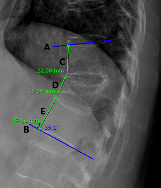 Fig. 1.. Five lines (A–E) of the thoracolumbar vertebrae in xray radiographs were determined. The Cobb angle was measured using the angle between the superior endplate of the vertebral body above… Source: Difference in the Cobb Angle Between Standing and Supine Position as a Prognostic Factor After Vertebral Augmentation in Osteoporotic Vertebral Compression Fractures — Neurospine 2022; CC BY-NC.
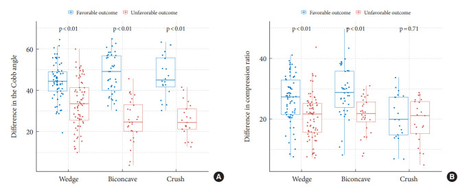 Fig. 5.. Boxplots with dot plots of the differences in the Cobb angle (A) and compression ratio (B) classified according to the shape of the fracture. Source: Difference in the Cobb Angle Between Standing and Supine Position as a Prognostic Factor After Vertebral Augmentation in Osteoporotic Vertebral Compression Fractures — Neurospine 2022; CC BY-NC.
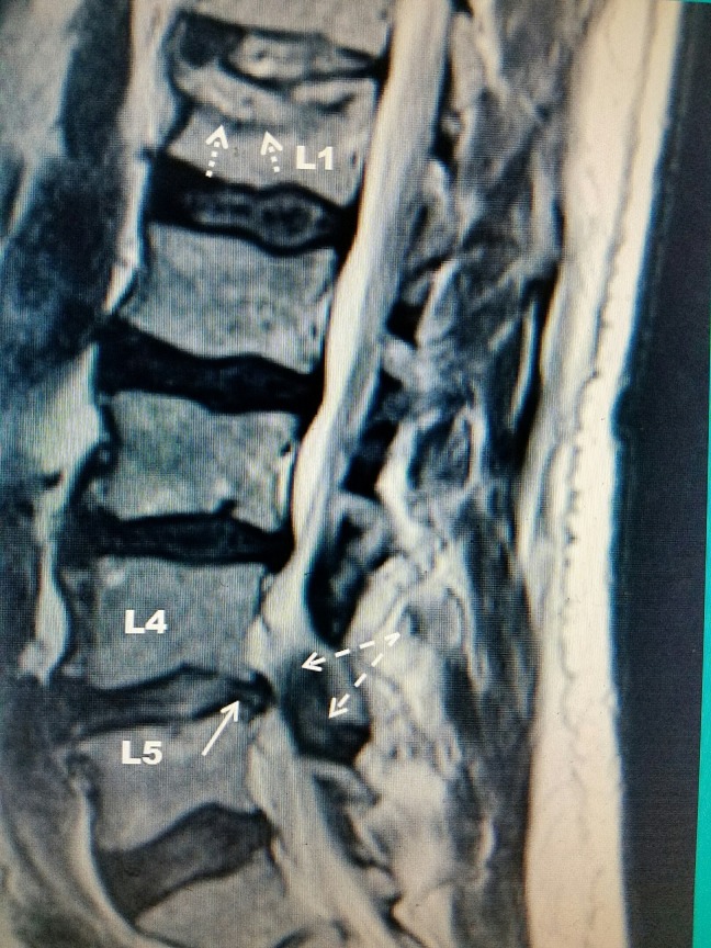 Figure 1. T2 weighted sagittal MRI demonstrating a L1 vertebral compression fracture in addition to L4/L5 central spinal stenosis Source: Evaluation and Interventional Management of Pain After Vertebral Augmentation Procedures — Cureus 2017; CC BY.
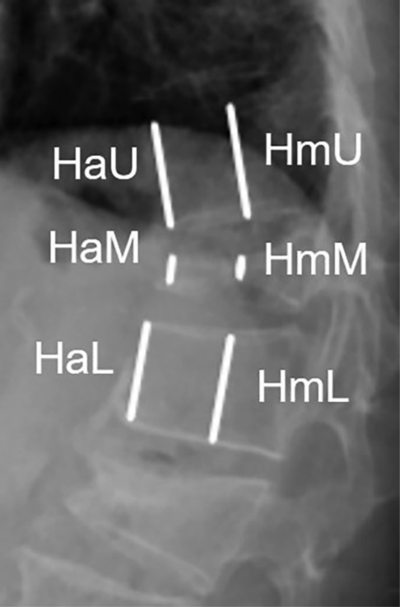 Figure 1. The measurement of body height. H = vertebral body height; M = the fracture vertebra; U = upper segment; L = lower segment; a = anterior part of the vertebra; m = middle part of the… Source: Percutaneous vertebral augmentation in special Genant IV osteoporotic vertebral compression fractures — Journal of Orthopaedic Translation 2020; CC BY-NC-ND.
History of Present Illness
- Chief complaint: Focal axial back pain at the fracture level, worse with movement/loading, point tenderness, limited mobility
- Acute/subacute fracture, failed conservative management (~2-6 weeks of analgesia, bracing) OR debilitating pain/immobility
- Etiology: osteoporotic (most), pathologic (metastasis, myeloma — augmentation for pain/stability), traumatic
- No neurological deficit (deficit/retropulsion with cord compression → consider open surgery instead)
Past Medical History
- Osteoporosis (DEXA), malignancy (pathologic fracture), steroid use, prior fractures
- Anticoagulation/antiplatelet (correct), coagulopathy
- Standard PMH
Imaging Review
MRI (STIR/T2)
- Marrow edema at the fracture level = acute/non-healed = likely to respond (old healed fractures don’t benefit); identify the symptomatic level among multiple fractures
- Posterior wall integrity/retropulsion, canal compromise (relative contraindication if significant), cord/cauda
- Pathologic features (mass, multilevel — myeloma/mets)
CT
- Fracture morphology, posterior wall/pedicle integrity (cement leak risk), bony anatomy for needle trajectory
X-ray (alignment, kyphosis)
Labs
- CBC, Coags (correct — needle, cement), BMP
- Malignancy workup if pathologic
Neurological Examination
- Focused: confirm no myelopathy/radiculopathy from retropulsion (would change plan), document baseline
Surgical Planning
Case Logistics, OR Needs & Orders
- OR table/bed: Jackson/Allen/open-frame radiolucent table, or ProAxis/hinged table when sagittal alignment adjustment is useful; keep abdomen free for venous decompression.
- OR setup: Jackson table, neuromonitoring, navigation/O-arm/fluoro, deformity implant trays, osteotomy tools, cell saver, blood products, warming, and positioning plan for long prone time.
- Special needs: arterial line, Foley, type/cross, tranexamic acid/blood-loss plan per protocol, MAP targets for cord perfusion, no long paralytic with MEPs, and postoperative brace/rehab plan.
- Immediate postop orders: ICU/step-down neuro checks, hemoglobin/coags, drain output, CT/X-rays alignment/hardware, MAP goal if high-risk correction, brace/activity, DVT prophylaxis timing, bowel regimen, and PT/OT.
Diagnosis & Indication
- Indication: Painful acute/subacute VCF (edema on MRI) refractory to/intolerant of conservative care; pathologic fracture pain/stabilization
- Contraindications/caution: asymptomatic/healed fracture, significant retropulsion with cord compression + deficit, uncorrectable coagulopathy, osteomyelitis at level, burst fracture with canal compromise
- Kyphoplasty (balloon creates cavity, may restore some height, lower-pressure cement fill) vs vertebroplasty (direct cement injection)
Fracture Selection Checklist
- Confirm the painful level: focal percussion pain, acute/subacute marrow edema/STIR signal, concordant uptake when nuclear imaging is used, and no better explanation for pain.
- Do not treat an old collapsed level just because it looks dramatic; chronic fractures without edema are common false targets.
- Review posterior wall integrity, pedicle anatomy, canal compromise, epidural tumor, infection, and coagulopathy before deciding augmentation is enough.
- In malignancy, obtain biopsy when diagnosis is unknown or progression pattern is unexpected; coordinate radiation/oncology timing.
- In osteoporosis, the procedure is only one part of treatment: bone-health therapy is what prevents the next fracture.
Kyphoplasty Versus Vertebroplasty
- Kyphoplasty may help when partial height restoration, cavity creation, or lower-pressure cement fill is desirable.
- Vertebroplasty is efficient for painful stable fractures where height restoration is not the goal and cement can be injected safely.
- Severe vertebra plana, burst morphology, major retropulsion, or posterior wall violation can make either procedure unsafe or less useful.
Position & Anesthesia
- Prone, fluoroscopy (biplanar), local + sedation (MAC) or general; padded
Key Surgical Steps
- Biplanar fluoroscopic localization of the level and pedicles
- Transpedicular (or extrapedicular) needle/trocar placement into the vertebral body under fluoroscopy (uni- or bipedicular) — stay within the pedicle (medial wall = canal; inferior = root)
- Kyphoplasty: inflate balloon tamp to create a cavity (± height restoration), deflate, then inject PMMA cement under low pressure into the cavity Vertebroplasty: inject PMMA directly into the cancellous bone
- Inject cement under continuous live fluoroscopy — stop immediately if any leak toward the canal/foramen/veins
- Allow cement to cure, remove instruments
- (Pathologic: may biopsy the lesion through the same access first)
Critical Anatomy & Structures at Risk
- Pedicle walls — medial breach → canal/cord; inferior → exiting root
- Posterior vertebral wall — cement leak into the canal (cord/root compression) — the principal serious risk
- Basivertebral/epidural/segmental veins — cement venous embolism (pulmonary)
- Adjacent disc/foramen (leak)
Equipment
- Kyphoplasty/vertebroplasty kit (trocars, balloon tamps, cement delivery), PMMA cement (high-viscosity)
- Biplanar fluoroscopy (essential), biopsy needle (pathologic)
Anesthesia
- Local + MAC (common) or general; prone; monitor for cement embolism (hypoxia, hemodynamic change)
Potential Complications
- Cement leak — epidural/foraminal (neural compression, radiculopathy/myelopathy), discal, venous
- Pulmonary cement embolism, rarely cardiac
- Adjacent-level fracture (altered biomechanics — common in osteoporosis)
- Pedicle breach/neural injury, infection, hematoma, no pain relief (wrong level/old fracture)
Cement Leak and Failure Rescue
- Leak toward canal/foramen: stop injection immediately, wait for viscosity/cure, redirect only if a safe path remains, and obtain urgent imaging for any new radiculopathy/myelopathy.
- Venous leak: stop injection, allow cement to harden, monitor oxygenation/hemodynamics, and evaluate for pulmonary cement embolism if respiratory symptoms occur.
- Pedicle breach: withdraw/reposition before cement, confirm AP/lateral trajectory, and do not inject if the cannula cannot be kept safely intraosseous.
- No pain relief: reassess level concordance, chronicity, adjacent fracture, malignancy, infection, stenosis/radiculopathy, and non-spinal pain sources.
- Adjacent fracture: treat bone health aggressively and image new pain early; repeat augmentation only when the new level is acute and concordant.
Operative Note Template
Preoperative Diagnosis: Painful [osteoporotic/pathologic] [T_/L_] vertebral compression fracture (acute, edema on MRI)
Postoperative Diagnosis: Same
Procedure: [Balloon kyphoplasty / Vertebroplasty] at [T_/L_] [with biopsy]
Surgeon / Assistant: Anesthesia: [Local + MAC / general] EBL / Fluids: Minimal Adjuncts: Biplanar fluoroscopy Implants: PMMA cement [± biopsy needle] Complications: None
Indications: [Age]yo [M/F] with a painful [osteoporotic/pathologic] VCF at [T_/L_] (marrow edema on MRI) refractory to conservative care, without retropulsion/cord compression. Risks (cement leak, embolism, adjacent fracture) discussed.
Description of Procedure: After consent and time-out, [local anesthesia with sedation] was given and the patient positioned prone with biplanar fluoroscopy. The level and pedicles were localized. A transpedicular trocar was advanced into the vertebral body under fluoroscopy, staying within the pedicle (protecting the medial wall/canal and the exiting root). [Kyphoplasty: a balloon tamp was inflated to create a cavity (± height restoration) and deflated.] PMMA cement was injected under continuous live fluoroscopy at low pressure, with vigilant surveillance for any leak toward the canal/foramen/veins; injection was stopped appropriately and the cement allowed to cure. [A biopsy was obtained through the access for the pathologic fracture.]
Instruments were removed and the patient recovered supine for cement curing, then assessed neurologically and for pain relief.
Postoperative Plan
- Recovery/observation (often same-day discharge); lie supine ~1-2h (cement cure)
- Neuro checks (new deficit → imaging for cement leak), pain assessment (often rapid relief)
- Osteoporosis management (calcium, vitamin D, anabolic/antiresorptive agents — prevent adjacent fractures), DEXA, endocrine/bone clinic
- Pathologic: oncology, address primary, consider RT
- Mobilize, follow-up; counsel re: adjacent-level fracture risk
Chief-Level Case Review
Use these as the senior-level mental model for Vertebral Augmentation (Kyphoplasty / Vertebroplasty):
- Decision point: Localize twice and instrument once: numbering, transitional anatomy, prior hardware, rib count, navigation dataset, and fluoroscopic level confirmation are mandatory.
- Technical lever: Positioning is treatment: table choice, abdomen-free prone setup, alignment goals, shoulders/hips, eyes/plexus pressure, neuromonitoring baselines, and fluoroscopic access all change the case.
- Bailout: Protect neural elements by sequence: decompression before correction when needed, MAP support for cord risk, no long paralytic with MEPs, and immediate response to signal change.
- Postop watch: Finish with construct logic: decompression adequacy, screw purchase, alignment, fusion bed/graft, drain plan, brace/activity orders, postop CT/X-rays, and DVT timing.
Common Pimp Questions
Use these to pressure-test preparation for Vertebral Augmentation (Kyphoplasty / Vertebroplasty):
- What neurologic level and root are responsible for the presenting deficit?
- What is the decompression target and how will you know it is adequately decompressed?
- What instability, deformity, bone-quality, or fusion variable changes the construct?
- What vascular, visceral, dural, or neural structure is the main structure at risk?
- What postop brace, drain, mobilization, MAP, antibiotic, and DVT plan should be ordered?
Attending Preference Variables
Items that commonly vary by surgeon or institution:
- Positioning frame, arms, traction, and localization workflow: [attending-specific]
- Navigation/robot/fluoro use, screw system, graft/biologic choice, and drain threshold: [attending-specific]
- Neuromonitoring modality and MAP goal for myelopathy, deformity, or cord-risk cases: [attending-specific]
- Brace, Foley, antibiotics, mobilization, and DVT prophylaxis timing: [attending-specific]