Case Prep: External Ventricular Drain (EVD) Placement
Case / Approach Snapshot
- Anatomy at risk: entry point, ventricular target, choroid plexus and deep veins, cortical vessels, eloquent cortex/tracts, catheter path, and distal hardware route.
- Operative steps: confirm indication and side, plan trajectory, prepare hardware, access ventricle or cistern safely, confirm flow/position, tunnel/connect devices when needed, and define infection/obstruction surveillance; use the detailed operative sequence and approach notes below as the step-by-step source.
- Rescue plans: malposition, hemorrhage, poor CSF return, overdrainage/underdrainage, obstruction, infection, abdominal/pleural complication, slit ventricles, and revision algorithm.
- Figures: review Figures, Imaging & Video and the Curated Image Set; embedded local figures should remain open-access, public-domain, or otherwise reusable with attribution.
- Papers: review High-Yield Literature for seminal sources, modern reviews, and outcome data specific to this page.
One-Liner
[Age]yo [M/F] with [acute hydrocephalus / SAH / IVH / posterior fossa mass / TBI] presenting with [decreased consciousness / headache / CN VI palsy / upward gaze palsy] planned for emergent/urgent right frontal EVD placement.
Figures, Imaging & Video
🎥 Operative videos & resources
- Technique searches: EVD placement / ventriculostomy on YouTube · freehand ventriculostomy technique
- Imaging review: Radiopaedia — EVD · Radiopaedia — hydrocephalus
- Open-access anatomy/technique: PubMed Central — EVD Kocher point
High-Yield Literature
- External ventricular drain management in subarachnoid haemorrhage: a systematic review and meta-analysis — Palasz J. Neurosurgical review 2022. PubMed
- External Ventricular Drain Misadministration Events: Systematic Literature Review and Report of a Case — Abramyan A. Operative neurosurgery (Hagerstown, Md.) 2024. PubMed
- Is Image Guidance Essential for External Ventricular Drain Insertion? — Fisher B. World neurosurgery 2021. PubMed
- Effect of External Ventricular Drain Tunnel Length on Cerebrospinal Fluid Infection Rates-A Bayesian Network Meta-Analysis — Garg K. World neurosurgery 2022. PubMed
- Risk Factors of External Ventricular Drain Infection: Proposing a Model for Future Studies — Sorinola A. Frontiers in neurology 2019. PubMed
- Silver-impregnated external-ventricular-drain-related cerebrospinal fluid infections: a meta-analysis — Atkinson RA. The Journal of hospital infection 2016. PubMed
- Impact of an External Ventricular Drain Placement and Handling Protocol on Infection Rates: A Meta-Analysis and Single Institution Experience — Sieg EP. World neurosurgery 2018. PubMed
- Rapid Versus Gradual Weaning of External Ventricular Drain: A Systematic Literature Review and Meta-analysis — Ebel F. Neurocritical care 2023. PubMed
- Chlorhexidine dressings could reduce external ventricular drain infections: results from a systematic review and meta-analysis — Waqar M. The Journal of hospital infection 2021. PubMed
- Management of external ventricular drain: to wean or not to wean? — Hallenberger TJ. Acta neurochirurgica 2024. PubMed
Curated Image Set
Open-access figures are embedded from PubMed Central articles and kept unique to this guide.
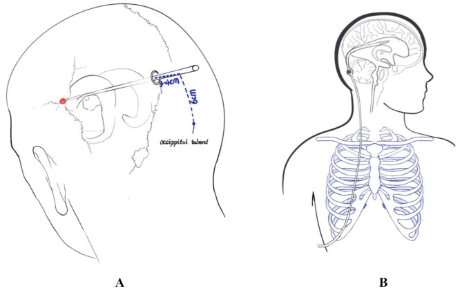 Fig. 1. (A) The puncture position of M-EVD group. (B) The position of the drainage tube in the M-EVD group Source: Clinical characteristics and post-operative outcomes in children with purulent meningitis with hydrocephalus: 46 cases in a single center study — Italian Journal of Pediatrics 2025; CC BY-NC-ND.
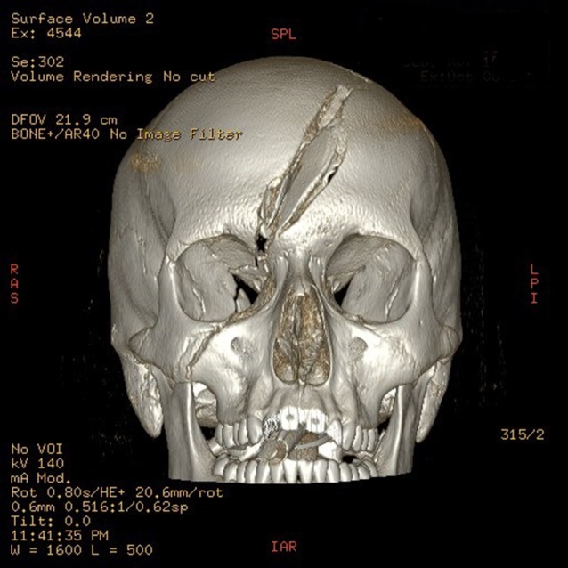 Figure 1:. 3D reconstruction of fractured skull. Source: Traumatic cerebrospinal fluid oculorrhea managed with an external ventricular drain — Journal of Surgical Case Reports 2018; CC BY-NC.
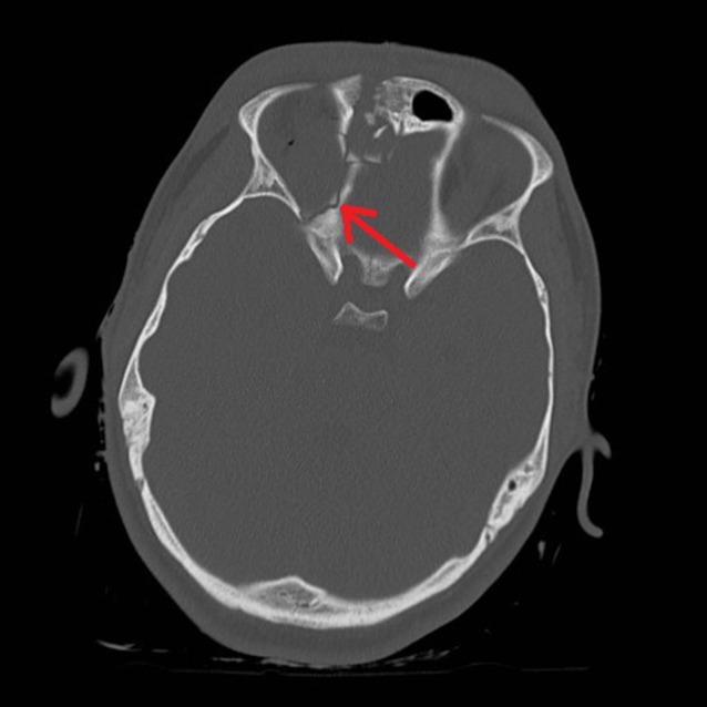 Figure 2:. Right medial orbital wall fracture showing route of CSF leak. Source: Traumatic cerebrospinal fluid oculorrhea managed with an external ventricular drain — Journal of Surgical Case Reports 2018; CC BY-NC.
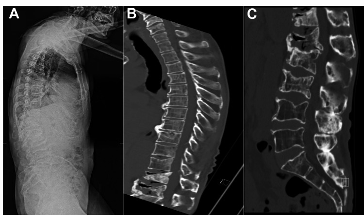 Figure 1. Scoliosis standing X-ray shows significant positive balance with pronounced thoracic kyphosis (A). Sagittal CT without contrast show T12, L1, L2, and L3 compression fractures with severe… Source: Use of an External Ventricular Drain for Treatment of a Thoracolumbar Cerebrospinal Fluid Leak: A Case Report and Review of Literature — Cureus 2022; CC BY.
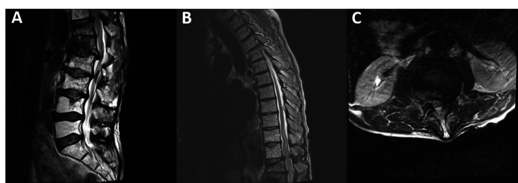 Figure 2. Sagittal (A & B) and axial (C) pre-operative MRI show severe compression at the level of T12 and L1. Source: Use of an External Ventricular Drain for Treatment of a Thoracolumbar Cerebrospinal Fluid Leak: A Case Report and Review of Literature — Cureus 2022; CC BY.
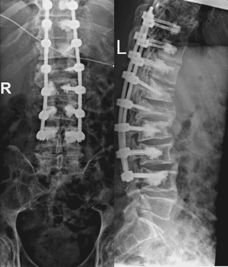 Figure 3. Post-operative X-rays show well-seated T9-L4 posterolateral instrumentation with cement augmentation. Source: Use of an External Ventricular Drain for Treatment of a Thoracolumbar Cerebrospinal Fluid Leak: A Case Report and Review of Literature — Cureus 2022; CC BY.
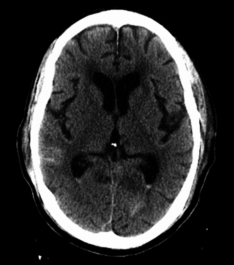 Figure 4. Post-operative CT of the brain without contrast shows scattered subarachnoid blood with some layering on the lateral ventricles along with small amounts of pneumocephalus. Source: Use of an External Ventricular Drain for Treatment of a Thoracolumbar Cerebrospinal Fluid Leak: A Case Report and Review of Literature — Cureus 2022; CC BY.
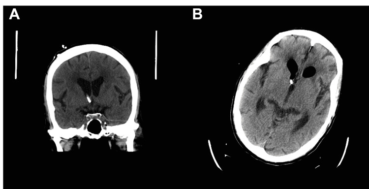 Figure 5. Coronal (A) and axial (B) CT of the brain without contrast showing proper placement of an external ventricular drain. Source: Use of an External Ventricular Drain for Treatment of a Thoracolumbar Cerebrospinal Fluid Leak: A Case Report and Review of Literature — Cureus 2022; CC BY.
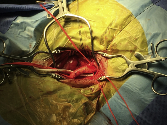 Fig 1. External ventricular drain (EVD) introduced posterior to retractors and left common carotid artery. Source: External ventricular drain as a nontraumatic suction device in carotid endarterectomy — Journal of Vascular Surgery Cases and Innovative Techniques 2017; CC BY-NC-ND.
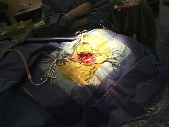 Fig 2. External ventricular drain (EVD) connected to regulated suction device. Source: External ventricular drain as a nontraumatic suction device in carotid endarterectomy — Journal of Vascular Surgery Cases and Innovative Techniques 2017; CC BY-NC-ND.
History of Present Illness
- Chief complaint: Altered mental status / headache / vomiting / visual changes
- Indication for EVD:
- Acute obstructive hydrocephalus (posterior fossa mass, aqueductal stenosis)
- SAH with hydrocephalus (acute communicating)
- IVH (intraventricular hemorrhage) — clot burden, hydrocephalus
- TBI with ICP monitoring indication (GCS <= 8 with abnormal CT)
- ICH with IVH and hydrocephalus
- CSF diversion (temporizing before definitive shunt)
- CSF sampling (infection workup)
- GCS:
- Pupils:
- Time course:
Imaging Review
CT Head
- Ventricle size: Enlarged (temporal horn dilation is early sign)
- Frontal horn index: Frontal horn width / biparietal diameter (> 0.3 suggests hydrocephalus)
- Third ventricle size:
- Temporal horn dilation: > 2 mm is abnormal
- Periventricular lucency: Transependymal flow (acute hydrocephalus)
- Cause: SAH, IVH, mass effect, aqueductal obstruction
- Midline shift:
- Target: Ipsilateral frontal horn (ideally right side / non-dominant hemisphere)
- Cortical mantle thickness at planned trajectory
Labs
- CBC (Plt > 50K minimum, ideally > 100K)
- Coags (INR < 1.4, PTT normal) — correct coagulopathy before procedure
- BMP
- Blood cultures (if infection suspected)
Surgical Planning
Case Logistics, OR Needs & Orders
- OR setup: bedside sterile kit or OR setup, navigation/ultrasound when anatomy is distorted, antibiotic-impregnated catheter when used, pressure transducer/drain system primed, and CT path ready.
- Special needs: coagulation/platelets corrected, antibiotics before incision, ICP/CPP goals, EVD height and drain/clamp order written explicitly, CSF culture plan if infection suspected, and sedation/airway plan for unstable patients.
- Immediate postop orders: ICU neuro/ICP checks, EVD level and hourly output/ICP documentation, CT head confirmation, CSF sampling rules, antibiotics per protocol, clamp-call parameters, and DVT timing.
Technique Selection
- Freehand (Kocher’s point): Standard bedside/OR technique
- Image-guided: Navigation-assisted (if available and time permits)
- Posterior (Frazier’s point / Keen’s point): Alternative sites for specific anatomy
Kocher’s Point (Standard Right Frontal)
- Location: 11 cm posterior to nasion (1 cm anterior to coronal suture) AND 3 cm lateral to midline (mid-pupillary line)
- Side: Right (non-dominant hemisphere) unless:
- Right-sided pathology (hemorrhage, mass)
- Prior right-sided surgery
- Specific anatomical reason to use left
- Trajectory:
- In the coronal plane: Aim toward the medial canthus of the IPSILATERAL eye
- In the sagittal plane: Aim toward a point just anterior to the ipsilateral tragus (or toward the external auditory meatus)
- Alternative: Aim toward the nasion in both planes (simplified)
- The target is the ipsilateral foramen of Monro (at the junction of the frontal horn and third ventricle)
Key Surgical Steps
- Confirm indication and side — time-out
- Position: Supine, HOB 30 degrees, head neutral or slightly elevated
- Mark Kocher’s point: 11 cm posterior to nasion, 3 cm lateral to midline (right side)
- Confirm: anterior to coronal suture (palpate)
- Confirm: at or near mid-pupillary line
- Prep and drape — wide sterile field around the entry point
- Local anesthesia — 1% lidocaine with epinephrine at the scalp site (if bedside)
- Incision: Small stab incision (~2 cm) at Kocher’s point through skin and galea
- Drill: Twist drill or hand drill through the skull
- Hold drill perpendicular to skull surface initially
- “Give” is felt when inner table is penetrated — STOP advancing
- Coagulate and incise dura — with monopolar or #11 blade
- Insert catheter:
- Pass ventricular catheter (stylet in) directed toward:
- Ipsilateral medial canthus (coronal plane)
- Ipsilateral tragus (sagittal plane)
- Advance to 5-5.5 cm from the inner table of the skull (typical depth to reach frontal horn)
- NEVER advance beyond 6-7 cm — risk of deep structure injury
- Remove stylet — CSF should flow
- If no CSF at 5.5 cm:
- Withdraw catheter, redirect slightly
- Do NOT make more than 3 passes (increases hemorrhage risk)
- If failed: consider image-guided placement or contralateral attempt
- Pass ventricular catheter (stylet in) directed toward:
- CSF return: Note color (clear, bloody, xanthochromic), opening pressure
- Tunnel catheter subcutaneously (~5 cm from the burr hole) to a separate exit site
- Connect to drainage system:
- Calibrated drainage column
- Set initial drainage level (typically 15-20 cm H2O above the tragus)
- Zero the transducer at the level of the tragus (approximates foramen of Monro)
- Secure catheter — suture to scalp at entry and exit points
- Sterile dressing over all sites
- CT head post-procedure — confirm catheter tip position (ideally in frontal horn, near foramen of Monro)
Catheter Tip Target
- Ideal: Ipsilateral frontal horn, tip at or near the foramen of Monro
- Acceptable: Anywhere in the ventricular system draining CSF
- Unacceptable: In brain parenchyma, too deep (in third ventricle or deeper)
Alternative Sites
- Frazier’s point (posterior): 6 cm above inion, 4 cm lateral to midline; aim toward supraorbital ridge
- Used for occipital approach, posterior fossa pathology
- Keen’s point: 2.5 cm posterior and 2.5 cm superior to pinna; aim toward contralateral medial canthus
- Used when frontal approach contraindicated
Critical Anatomy & Structures at Risk
- Eloquent cortex — frontal lobe at entry site (Kocher’s point is chosen to avoid motor cortex)
- Superior sagittal sinus — entry point must be > 2 cm lateral to midline
- Motor cortex (precentral gyrus) — posterior to Kocher’s point; do not place too posteriorly
- Caudate nucleus / thalamus — if catheter advanced too deep
- Choroid plexus — can occlude catheter
- Cortical vessels — at entry site; cannot be avoided, but small caliber usually
Equipment
- EVD kit (catheter, stylet, drainage system, tunneling rod)
- Twist drill or hand drill
- Sterile drapes and prep
- #11 blade scalpel
- Local anesthesia (1% lidocaine with epinephrine)
- Monopolar cautery (for dura)
- Suture (2-0 silk or nylon)
- Sterile dressing materials
- Measuring tape or ruler
Potential Complications
- Hemorrhage — intracerebral or intraventricular (~5%); limit to <= 3 passes; correct coagulopathy
- Misplacement — parenchymal, extra-ventricular; CT confirms position
- Infection (ventriculitis) — 5-10% risk; decreases with tunneling, antibiotic-coated catheters, strict sterile technique
- Overdrainage — collapsed ventricles, subdural hematoma, upward herniation (posterior fossa mass); set appropriate drainage height
- Catheter obstruction — blood, debris, choroid plexus; may need flushing or replacement
- Pneumocephalus — from open drainage system; keep system closed
Operative Note Template
Preoperative Diagnosis: [Acute hydrocephalus / SAH with hydrocephalus / IVH / TBI requiring ICP monitoring]
Postoperative Diagnosis: Same
Procedure: Right frontal external ventricular drain placement via Kocher’s point
Surgeon: Anesthesia: [General / MAC / local with sedation]
EBL: Minimal Fluids: Drains: Right frontal EVD Complications: None
Indications: The patient is a [age]yo [M/F] with [indication] and CT head demonstrating [findings including ventricular enlargement]. An EVD was indicated for [CSF diversion / ICP monitoring / both].
Description of Procedure: After informed consent [was obtained / was waived due to emergent nature], a time-out was performed. The patient was positioned supine with the head of bed at 30 degrees and the head in neutral position. Kocher’s point was marked on the right side at 11 cm posterior to the nasion and 3 cm lateral to midline, confirmed to be anterior to the coronal suture and at the mid-pupillary line.
The right frontal region was prepped and draped in sterile fashion. [Local anesthesia was administered.] A [2 cm] incision was made at Kocher’s point. A twist drill hole was created perpendicular to the skull surface. The dura was coagulated and incised.
The ventricular catheter with stylet was passed aiming toward the ipsilateral medial canthus in the coronal plane and the ipsilateral tragus in the sagittal plane. CSF was obtained at a depth of [__] cm from the inner table. The stylet was removed. [Opening pressure was __ cm H2O.] [CSF appeared clear/bloody/xanthochromic.]
The catheter was tunneled subcutaneously [5 cm] from the burr hole and secured at both the entry and exit sites with 2-0 [silk/nylon] sutures. The catheter was connected to the external drainage system and set to drain at [15-20] cm H2O above the tragus. A sterile dressing was applied.
Postoperative: CT head obtained to confirm catheter tip position [in the right frontal horn / at the foramen of Monro]. ICP was noted to be [___] mmHg.
Postoperative Plan / EVD Management
- ICU with continuous ICP monitoring
- Neuro checks q1h
- EVD drain level: Set at ___ cm H2O above the tragus (typical: 15-20)
- Wean protocol: Gradually raise drain level (e.g., increase by 5 cm H2O q12-24h)
- Clamp trial: Once at 20-25 cm, clamp for 24h → if ICP stable (< 20) and clinically well → consider removal
- Record output: q1h; document volume, color, and clarity
- ICP alarms: Set upper limit (typically 20-22 mmHg)
- CSF sampling: Send daily or per protocol (cell count, glucose, protein, culture)
- Surveillance for ventriculitis: increasing WBC count, decreasing glucose, positive culture
- Infection prevention:
- Minimize catheter access/manipulation
- Sterile technique for any sampling
- Keep system closed
- Daily site inspection
- No routine catheter changes
- CT head: Daily or per clinical change to monitor ventricle size
- Duration: Attempt to remove as soon as possible (infection risk increases with time)
- Typical: 5-14 days depending on indication
- Transition to definitive CSF diversion: VP shunt or ETV if unable to wean EVD
- Removal: When clamp trial successful for 24-48h
- Remove at bedside: Pull catheter, purse-string suture on skin, pressure dressing
- CT head after removal
Chief-Level Case Review
Use these as the senior-level mental model for External Ventricular Drain (EVD) Placement:
- Decision point: Trajectory and hardware choice should follow the failure mode: obstruction, infection, overdrainage, loculation, slit ventricle, distal failure, or wrong pressure setting.
- Technical lever: Document the system: entry point, catheter target/depth, valve type and setting, distal site, antibiotic-impregnated hardware, and what imaging confirms placement.
- Bailout: Rescue plan is practical: poor CSF return, bloody CSF, malposition, distal access failure, abdominal/pleural complication, or inability to safely pass the catheter.
- Postop watch: Postop orders must be unambiguous: drain height/rate/max output, valve setting, clamp parameters, imaging, antibiotics, ICP/neuro checks, and overdrainage precautions.
Common Pimp Questions
Use these to pressure-test preparation for External Ventricular Drain (EVD) Placement:
- What is the working CSF physiology problem: obstruction, absorption failure, overdrainage, infection, or catheter failure?
- Where exactly is the entry point, target, and backup trajectory?
- What valve, catheter, endoscope, or navigation preference does the attending use?
- What is the infection-prevention plan and what cultures/CSF studies are needed?
- What postop imaging, valve setting, drainage level, and neuro-check plan should be written?
Attending Preference Variables
Items that commonly vary by surgeon or institution:
- Valve brand/setting, antibiotic catheter use, and tunneling side: [attending-specific]
- Navigation/endoscope/stylet preference and ventricular target: [attending-specific]
- CSF culture/lab routine and perioperative antibiotic duration: [attending-specific]
- Postop scan timing, EVD height or valve verification, and activity restrictions: [attending-specific]